Introduction
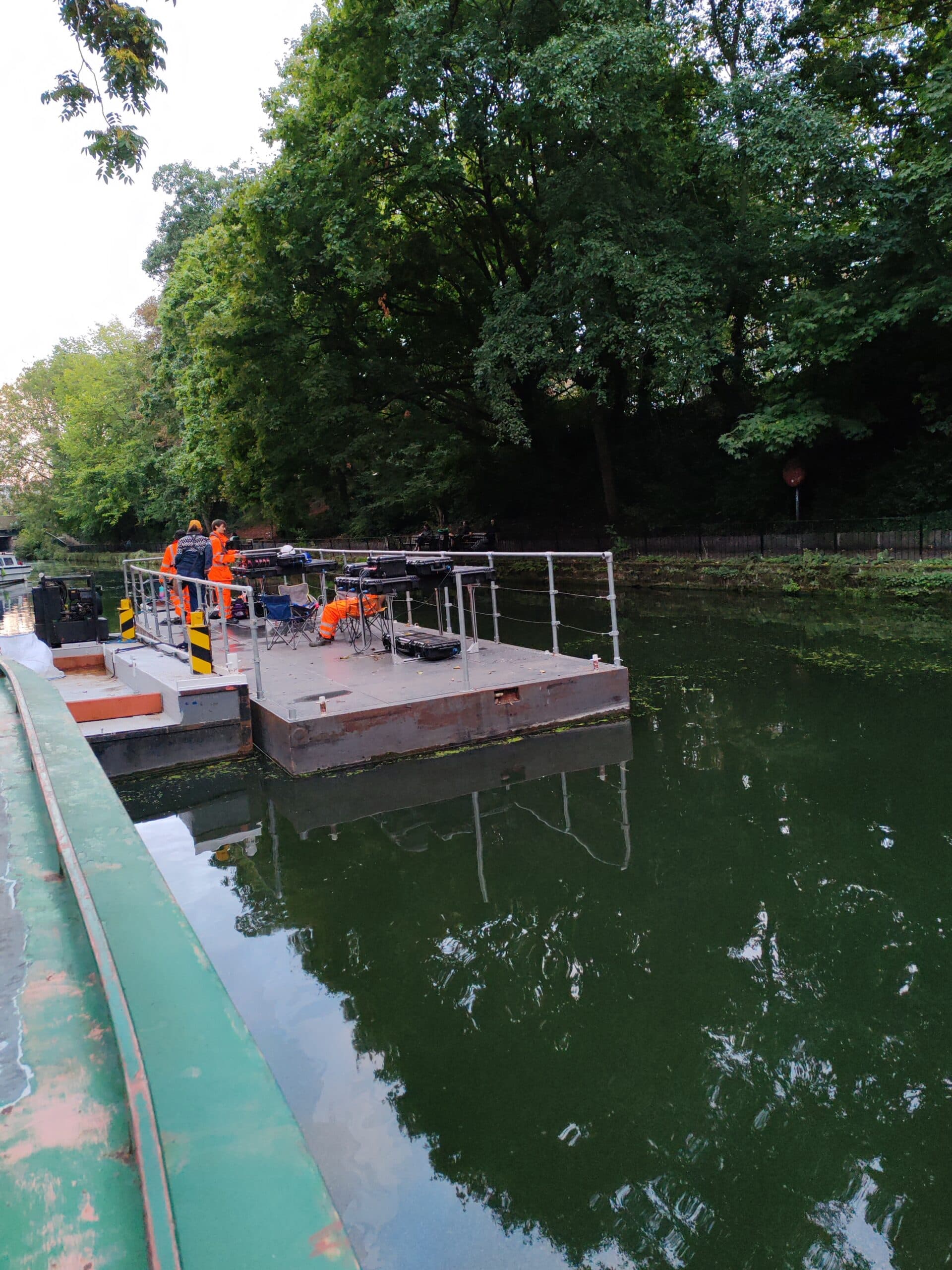
On a quiet stretch of a canal in London, a barge was moored with an unusual payload: Geoptic’s muon imaging detector. Rather than drilling or opening up the ground, Geoptic set out to use naturally occurring cosmic-ray muons to characterise density variations above the Canal Tunnel. Over successive nights of measurement, the instrument recorded the paths of muons passing through masonry and surrounding ground, building the dataset needed to apply Geoptic’s advanced inversion algorithms to produce a subsurface density model. This article follows that survey from barge set-up and alignment through to data processing and the types of tunnel-related features muography can help to identify.
What is Muon Imaging?

Muon imaging, often referred to as muography, is a passive geophysical technique that uses naturally occurring cosmic ray muons to estimate variations in density within large structures and the ground around them. Muons are high-energy particles produced when cosmic rays interact with the upper atmosphere. At ground level they arrive continuously from above and, because they are highly penetrating, many will pass through substantial thicknesses of masonry, soil, and rock.
A muon imaging detector measures the direction and rate of muons that reach it after travelling through the target volume. Where the muons have had to pass through denser material, fewer will arrive, and their trajectories may be altered more. Where the muons pass through lower-density regions, such as voids or less compacted ground, a higher flux is typically recorded. By collecting data over time and comparing the measured muon flux from different angles, it is possible to reconstruct a map or model of relative density.
Why use Muon Imaging for Canal Tunnel Surveys?
Canal tunnels are constrained environments. They are often historic assets, frequently underneath and surrounded by dense urban development, and difficult to access from the surface without disrupting transport routes, utilities, or neighbouring properties. When there is a need to understand what sits beyond the visible lining, within the surrounding ground, behind masonry, or above the crown, intrusive investigations can be costly, slow to permit, and difficult to carry out safely.
A survey approach based on muon imaging, also known as muography, addresses many of these constraints. The method relies on naturally occurring cosmic ray muons, so it does not require an artificial radiation source, active transmitters, or ground penetration. The detector records muon trajectories over time and, from the way muons are attenuated through the tunnel lining and surrounding ground, a density model can be reconstructed. This makes the technique well suited to locations where access is limited and the priority is to minimise intervention.
Using the canal itself as the survey platform adds a further practical advantage. A barge provides a stable, serviceable base with direct alignment along the tunnel corridor, allowing equipment to be positioned close to the structure without excavations or highway closures. It also supports controlled deployment, including power provision, environmental protection, and repeatable positioning, while keeping the work largely within the canal boundary.
The objective of surveying in this way is to obtain useful information with minimal disruption. Density deviations from expectation can be clearly identified, follow-up inspections can be better targeted, and confidence can be improved when planning maintenance and managing risk. In practice, muon imaging is most effective when interpreted alongside existing drawings, inspection records, and targeted verification, providing an additional line of evidence for understanding subsurface conditions around the tunnel.
Muon Imaging and Conventional Tunnel Survey Approaches
Traditional approaches to tunnel assessment tend to fall into two broad categories: direct inspection of the lining and intrusive or semi-intrusive investigation of the surrounding ground. Visual and close-up inspections can be highly effective for identifying defects that are exposed at the surface, such as cracking, spalling, leakage pathways, deformation, and condition of joints. Their limitation is that they primarily describe what can be seen, and they can require access arrangements, possessions, and working in confined conditions.
Non-Contact and Non-invasive
Muon imaging occupies a different position in the tunnel diagnostic toolkit. It is passive and non-intrusive, and it can be deployed where surface access is limited, as it does not require transmitters, coupling to the ground, or drilling. Instead, it builds up a picture of density by recording cosmic ray muons over time. The principal limitation is that it typically requires an exposure period to accumulate sufficient data. Muography is often used to highlight density anomalies that can guide targeted inspection and verification, rather than as a standalone replacement for established inspection and investigation methods.
Large Volume “X-ray” Beyond the Tunnel Lining
Where information is needed beyond the lining, intrusive methods such as boreholes, trial pits, core sampling, and probe drilling can provide a high-confidence ground truth, including material identification and laboratory testing. The trade-off is that these methods introduce disturbance, can be expensive to permit and mobilise in urban settings, and may only sample discrete points, leaving uncertainty between locations.
Insensitive to Ground Environmental Conditions
Ground-based geophysical techniques, including ground penetrating radar, electrical resistivity, and seismic methods, can help interpolate between points, but their performance is sensitive to ground conditions, access geometry, and site noise, and they can be challenging to deploy where the surface is constrained.
The Canal Barge Muography Survey Setup
Muon Survey Overview
The survey was carried out from a canal barge moored on the Canal in close proximity to the tunnel, positioned to maintain a clear line of sight through the volume of interest above the tunnel, and to align the detector with the tunnel heading direction. The location was selected to provide stable access along the canal edge and to allow the instrument to collect muon trajectories through the tunnel lining and overburden ground without requiring intrusive works from the tunnel or streets above.
A barge platform offered practical advantages for deployment. Working from the canal enabled the Geoptic team to position equipment close to the asset using an existing access route, while reducing the need for street works, traffic management, or excavation. It also provided space for mounting, power provision, and secure housing of instrumentation, supporting a controlled set-up in a constrained urban environment.
Geoptic’s Optimised Tunnel Survey System
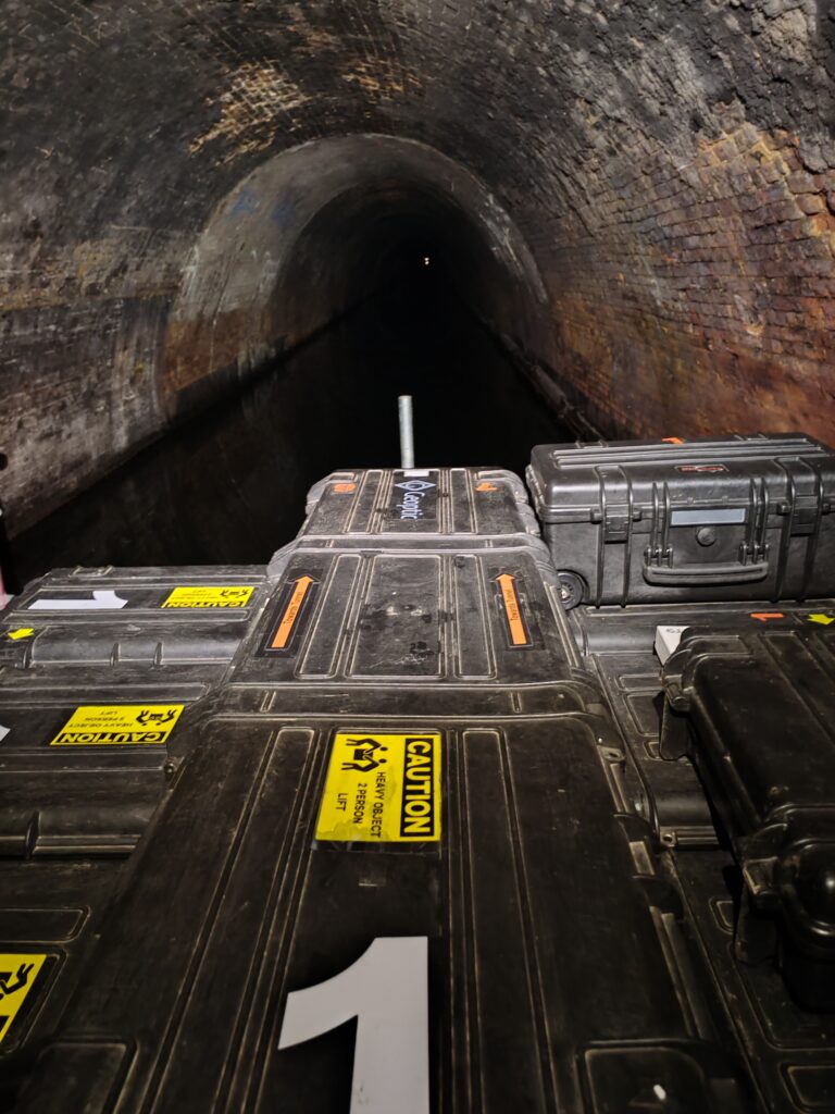
The detector configuration has been optimised for field operation and imaging for short access times of the order of a few hours. The system comprised muon tracking detectors mounted on a rigid frame and oriented to measure muon flux through the tunnel crown. The assembly was levelled with the barge and tunnel heading direction, with cables and detectors made secure on the framework. Power was supplied from the on-board battery, with continuous data logging to local storage and wireless control. Routine status checks were carried out throughout the deployment to ensure data quality and system stability.
Prior to subsurface measurements, comprehensive calibration procedures were conducted outside the eastern portal entrance. The survey methodology incorporated exposure times at each measurement position, with data acquired at intervals across regions of interest identified through archival research.
The data acquisition system recorded muon rates through multiple overlapping lines of sight, enabling tomographic reconstruction of overburden density distributions. Muon transmission values were calculated as the ratio between in-tunnel muon rates and baseline measurements, subsequently converted to values representing the integrated density along each muon trajectory path.
Survey Operations
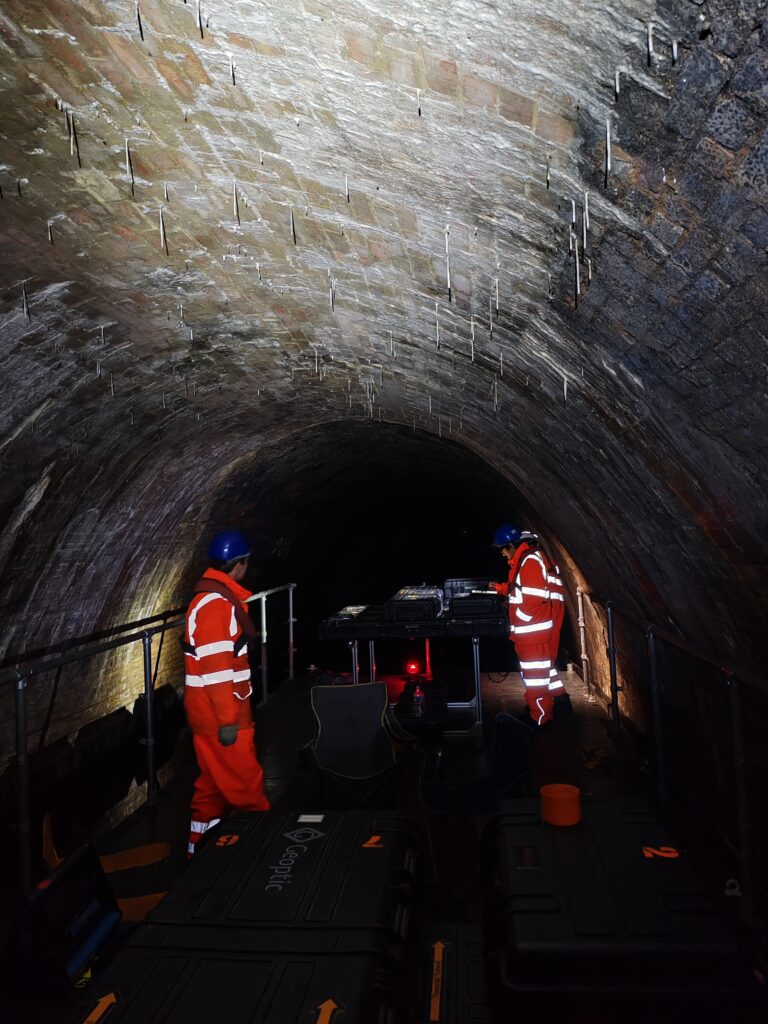
Vibration and minor motion were controlled and operational checks were used to identify any movement that could affect angular accuracy. In addition, for each run the barge was tied to mooring rings on the side of the tunnel. Moisture was mitigated using IP67 detector housings and protected cable runs, with attention to condensation risk. Temperature variation was monitored to maintain detector stability and support reliable calibration. Security was addressed through physical locking of equipment, discrete placement and signage where required, and an agreed access plan to minimise interference during unattended operation.
The survey operations were conducted during overnight shifts in September 2025, comprising over 40 measurement positions completed across two consecutive nights. Meteorological data were continuously recorded to account for temperature and pressure effects on muon flux rates. The urban environment above the Tunnel presented additional complexity, with Digital Surface Models (DSM) incorporated into the reconstruction algorithms to differentiate between subsurface geological features and overlying man-made structures.
The canal barge platform proved particularly advantageous for this application, providing stable positioning while minimising disturbance to the tunnel structure and enabling efficient progression between measurement locations. This deployment methodology demonstrates the adaptability of muon imaging technology for challenging subsurface investigations where conventional geophysical techniques may be limited by access constraints or environmental interference.
Key findings
- Most of the surveyed length showed density characteristics consistent with the expected host ground materials.
- Several discrete zones exhibited density contrasts not consistent with a single, uniform ground type.
- These anomalous zones were spatially localised and reproducible across different analysis configurations.
Interpretation
- The identified anomalies may be associated with changes in ground conditions, buried infrastructure, foundations, services, or historical interventions rather than uniform natural geology.
- Inclusion of surface building models reduced uncertainty and improved confidence in distinguishing genuine subsurface features from surface loading effects
Overall conclusion
The survey successfully demonstrated the ability of non-intrusive imaging to identify and spatially constrain subsurface anomalies above a canal tunnel in a dense urban environment. The results provide targeted evidence for follow-up investigations and asset-management planning, without the need for disruptive intrusive work.